Stereo 2-Way Passive Crossover with Extra Tweeter Outputs
A stereo “3-way” 130Hz passive crossover having 12dB per octave slope subwoofer outputs (2-4 ohm), 6dB per octave slope satellite outputs (4 ohm), and separate 2500Hz, 12 dB per octave slope tweeter outputs.
Meant to crossover a full range driver to a subwoofer driver, and in addition feed a back firing tweeter.
Optional baffle step compensation network
CMC 838-SG gold plated binding posts
Internal wiring using high grade Sonic Link speaker cables
Enables easy access to the crossover parts
Subwoofer outputs can together feed a single dual voice coil subwoofer driver
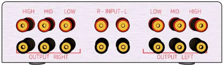
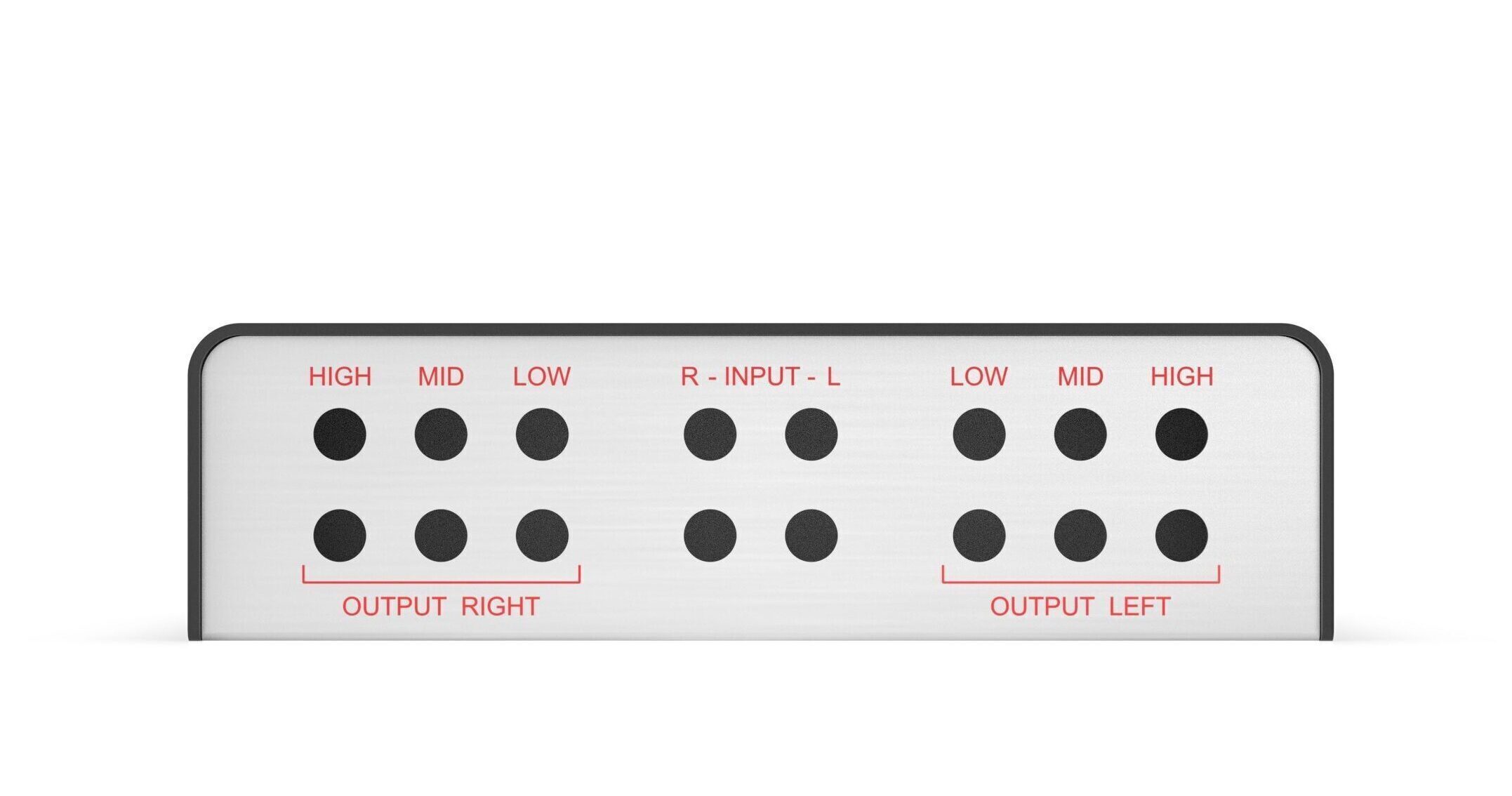
Low output: 0-130Hz Mid Outut: 130Hz and above High output: 2500Hz and above
a dual channel 130Hz crossover board that feeds two full range 4 ohm drivers (satellites) and two 2-4 ohm subwoofer drivers (or one dual voice coil driver). 12 dB/oct slope for the subwoofers 6 dB/oct slope for the satellites Handles up to 200 watts RMS
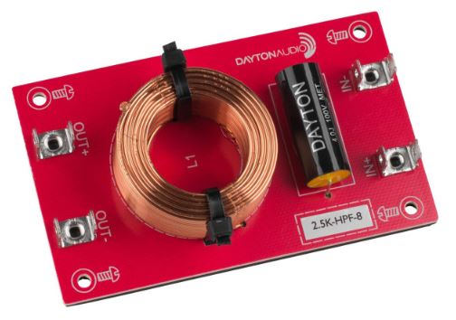
2500Hz, 12 dB/oct slope high pass filter that feeds a back firing tweeter (4 or 8 ohm by choice).
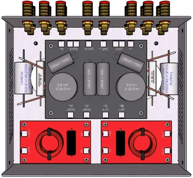
The grey board is a two channel 130Hz Woofer-Satellite crossover network. On its sides are two Baffle Step and High Frequency roll-off Compensation networks. The two red boards are 2500Hz high pass filters, each feeding a back firing tweeter.
Baffle Step and HF roll-off Compensation
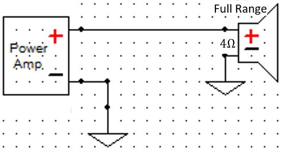
direct coupling
A full range driver connected directly to an amplifier. The blue curve shows the spectral energy distribution of the signal fed to the driver – a “flat” signal. It would also be the frequency response of an acoustically ideal driver mounted on an infinitely large flat baffle. When mounted in a box of average size, the driver’s on axis SPL gradually increases with frequency, starting at about 200Hz until stabilizing 6dB louder at about 800Hz (red curve). This increase in SPL is commonly referred to as “Baffle Step”.
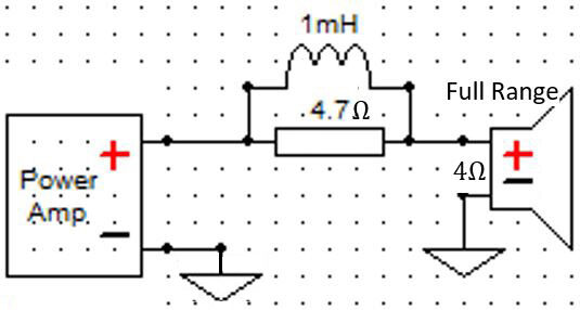
RL Compensation
The baffle step can be cancelled out by means of a shelving low pass network comprised of a resistance and an inductance. At low frequencies, the network presents a low series impedance and is therefore electrically transparent. As frequency increases, the network impedance increases too, leading to a weaker signal at the driver input. At still higher frequencies, the network impedance ceases to increase with frequency and stabilizes on its maximal value – the resistor value. Accordingly, the signal fed to the driver ceases to weaken and its level stabilizes.
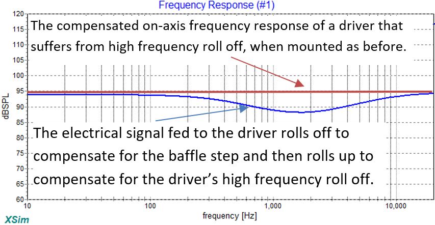
RLC Compensation
Most full range drivers suffer from a high frequency roll off. To compensate for that, a capacitor may be added to form an RLC network. The shelving low pass network now turns into a band stop network.
crossed over
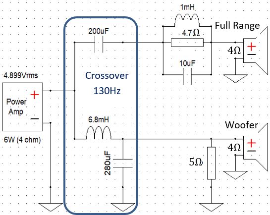
The full range driver is now crossed over at 130Hz to a subwoofer driver. The two drivers are positioned equidistantly from the listener and connected in opposite polarity.
The 1st order high pass filter (200uF series capacitor) rolls off the electrical input to the full range driver at a rate of 6dB per octave toward lower frequencies.
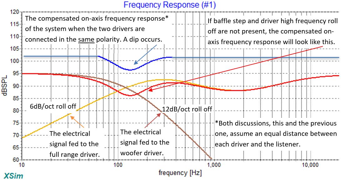
The 2nd order low pass filter (series inductor and shunt capacitor) rolls off the electrical input to the subwoofer driver at a rate of 12dB per octave toward higher frequencies.
Same as before, but here the two drivers are connected with identical polarity. A dip occurs in the frequency response due to acoustic phase cancellation between the outputs of the full range driver and the subwoofer driver.
If the distance between each driver and the listener is not the same, the dip becomes less prominent, until it practically disappears when the difference in distance approaches a half wavelength (130cm) of the crossover frequency.
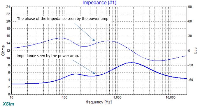
The magnitude and phase of the impedance presented to the amplifier.
At low frequencies the amplifier faces a low impedance of less than 3 ohms and should therefore have adequate current supply.
At about 2,000Hz the impedance peaks to almost 9 ohms, representing the lower amount of power drawn in this frequency range due to baffle step compensation.
Final thoughts
The “6dB per octave roll-off toward lower frequencies” of the electrical input to the full range driver, implies that its cone excursion “only” doubles with each halving of frequency instead of quadruples (what naturally happens when no crossover is used). A steeper roll-off toward lower frequencies, however, would be even better: A 12dB/oct roll-off would lead to an excursion that doesn’t increase as frequency decreases. An 18dB/oct roll-off would lead to an excursion that linearly decreases with frequency. A 24dB/oct roll-off would lead to an excursion that decreases fourfold with each halving of frequency.
An active crossover can readily provide a 24dB per octave roll-off, which results in a system that can produce high SPL without mechanically stressing the full range driver – arguably the main reason why to consider going active. Admittedly, the ability to comfortably control each driver’s output level as well as the degree of compensation (baffle step, and if a dipole woofer is used – also dipole compensation) is appealing, but in itself hardly justifies the extra cost and complexity involved. Unless high sound levels are required, a passive crossover as described here is certainly the reasonable way to go.